|
1. Failure of the bias device,
the TIP147 The main problem with this amplifier was the continuing failures of the TIP147 device. The fault presented itself as follows: The amplifier would load up OK, but initial tuning would produce a situation when the plate current would jump to about 1.2 to 1.3 amps and the heat output of the amplifier would rise dramatically, removing the RF drive and un-keying the amplifier had no effect. The only option available would be to kill the 240v supply. This would leave the amplifier with a red hot valve and no running blower! When presented with such symptoms the TIP147 will have failed. Replacing the device and trying the same tune up will result in another failure. The picture blow shows the TIP147 and associated heat-sink as originally fitted.
|
||
|
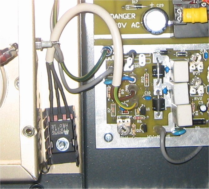
The TIP147 (it's the large black device, upside down on the left) is clamped to the underside of the anode compartment connected to a small heat-sink. (the size of the heat-sink compared to what is recommended in the triode board manual falls way beyond expectation and should have been put right at the manufacturing test stage!) I'd like to point out that this was the first time I noticed that the SEK control board hadn't been built as specified, you'll see ONE of two zena diodes located where the VDRs should be (Middle of the picture where it says DR1 just above where the blue wire is connected to the board!) Here's another shot of the same board.
One interesting point to note on the above picture is that following a warranty return visit to Linear Amp UK, the two back to back diodes were changed for what looks to be some sort of gas discharge device, as shown above (the white device with '05 o' on it. What was annoying at the time was the crude way the diodes were simply 'snipped' out) more on this below. |
||
|
The first trial at fixing the TIP147 problem was be using a decent heat-sink. (see below)
I tried the TIP147 on a larger heat-sink, bolting it firmly down, making sure that it was clamped for good heat transfer, but not electrically shorted to ground. This picture clearly shows how I had to move the control board to give room for the heatsink. Extra holes were drilled in the grid compartment to allow for cooling air to blow over the fins of the heat-sink. Sadly, this mod didn't work as the TIP147 failed yet again, but at least we'd removed the gas discharge device by this time, and refitted two VDRs. Unfortunately, this didn't help either. The next picture below shows what I tried next, an even better heat-sink. This one matched, or even bettered the recommendations by Ian, GM3SEK, and it was at this point I just wanted the amplifier to work, so wasn't to bothered about extras bolted on to the amp. Thus here is a picture of the TIP147 complete with heat sink and cooling fan. This is perhaps overkill, but at least it worked!
|
||
|
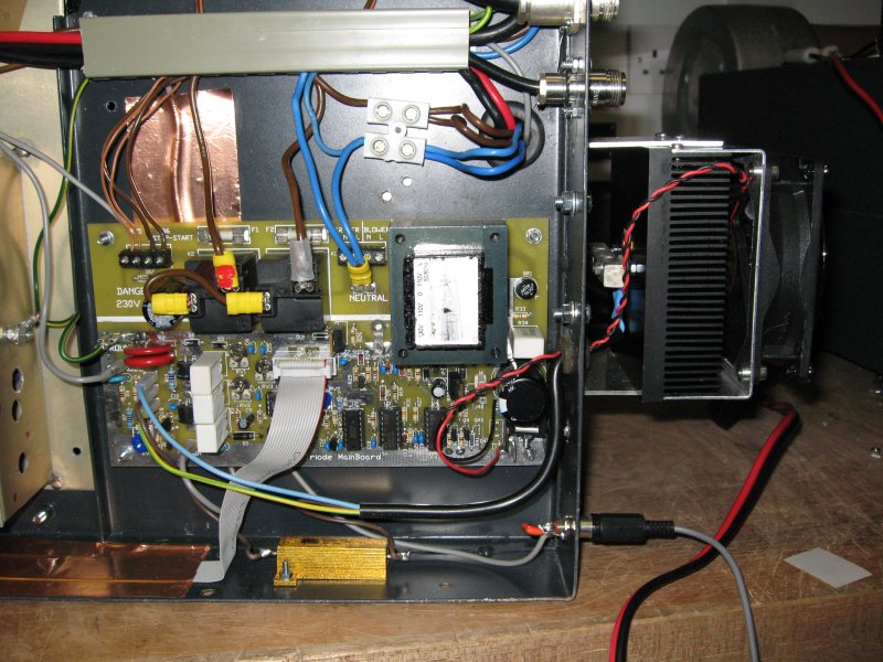
It was around this time that Ian, GM3SEK suggested that fitting a 50w, 10ohm resistor in line with the Q1C connection between the TIP147 and the main board would help. So, the picture below shows the resistor in place. It should be noted that fitting this resistor is just as important as the cooling heatsink and the fan as above!
|
||
|
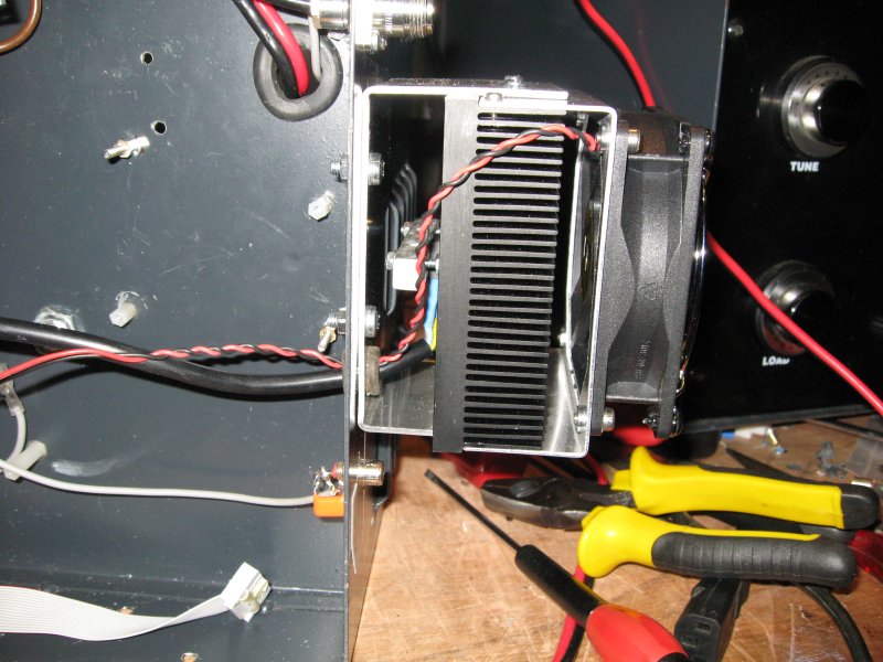
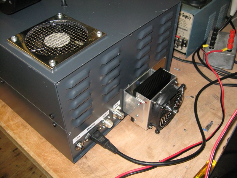
With everything now back in place, and the issue with the TIP147 now seemingly resolved, it was time to bolt everything back together again. Here's one final picture of the rear of the amplifier showing the TIP147 heatsink and fan.
If you have a linear amp UK amplifier that suffers from the same fault then if you fit a suitable heat sink to the TIP147 and fit a suitable resistor in line with Q1C as shown above, then your amplifier will work as advertised. Lots of information on the same TIP147 fault on a HF amplifier can be found here: |
||
| 2. Cooling inadequacies | ||
|
The standard fit blower must have been one of a 'job lot' as it's the same blower as fitted to most, if not all, of the Linear Amp UK amplifiers. The GS35b needs a minimum of 85CFM airflow, the blower fitted from new had a rating of 30.5 litres per second, now that sounds good, but when converting 30.5LPS to CFM, it turns out to be 64.6CFM, that's around 20CFM short of minimum! Note: These under cooling issues are concerned with the 2005 model amplifier, but it was interesting to see that the new GS35b amplifier from Linear Amp UK still uses this under sized blower.
|
||
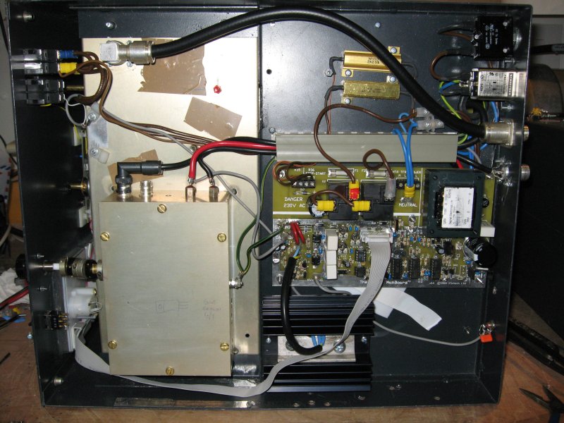
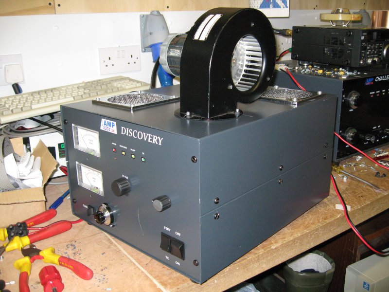
| The picture below shows my Linear Amp UK amplifier in it's current, finished state. The larger blower moves a lot more air than the original fit blower, and the tube no longer gets quite as warm. I admit it doesn't look as compact now, but you might consider this to be one of the 'beta test' units rather than an 'as built' amplifier. You can now also see how I have added the grid tune control knob on the front panel. | ||
|
|
||
|
With the amplifier now running with the improved blower, here is a small test I did, it's not very scientific, but it does show just how much more air is now flowing over the GS35b tube. The orange item is the lid off a paint spray can. |
||
| 3. Poor input match | ||
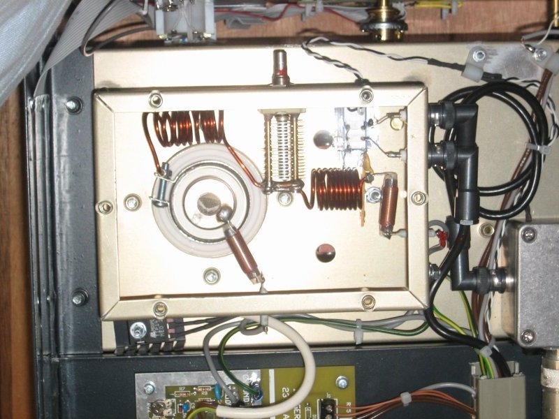
| The picture shown below shows a close up of the grid compartment, bottom left of the compartment is one half of the TX/RX relay, then there's the grid tuning capacitor & coils, and then the heater supply through two small chokes along the tube bias. The air space capacitor has since been changed, in my opinion when it was fitted it was rather brutally 'man handled' during the fitting of the coils, this in turn actually twisted the frame of the cap and resulted in it flashing over when adjusted! Not sure you believe me? I have a short video file of the cap while I tried to tune the input, and it shows how it flashed over. | ||
|
|
||
| The issue with the poor
match was never resolved whilst under warranty, my amplifier never,
ever, presented a good input match to my drive radio. The FT650 was
always presented with an SWR of 1.7:1 or worse. Even when the amplifier
spend some time back with the supplier this poor input match was never
resolved!
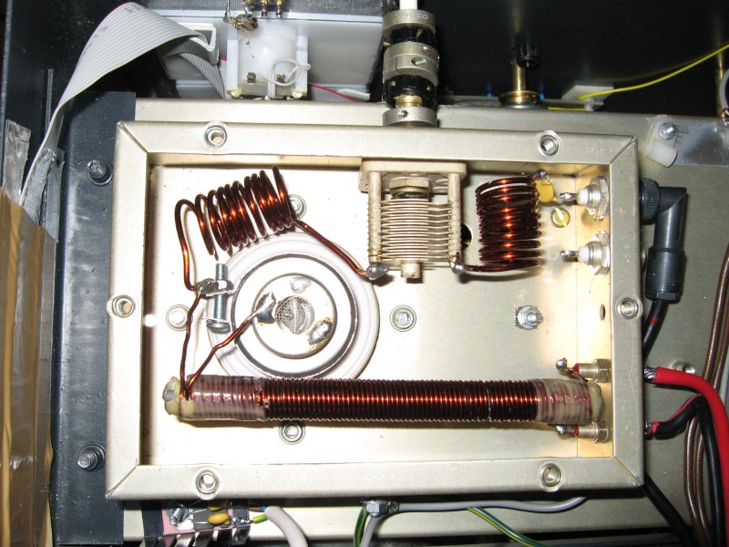
In the end, the answer to this problem turned out to be rather simple. This next picture shows the modifications I did in the grid compartment to improve the match. |
||
|
|
||
|
The first change was the grid tuning capacitor, as I've already mentioned, the capacitor was faulty so I swapped it out for a better quality device and one that wasn't twisted. The one major alteration that had the greatest effect on the input match was the move of the first coil (top right in both pictures). I'd read some comments on a web page written by Conrad, G0RUZ about grid match, so I moved the coil through 90 degrees and the input match is now perfect! The feed through capacitors for the heater supply were also changed to higher specification devices, and I upgraded the heater supply line (the red/black cable) it is also possible to see the addition of the external grid tune, this can now be adjusted via the front panel. This is something that I consider to be essential on any amplifier of this design. Another alteration that can be seen in the picture above is the large bifilar wound choke for the heaters. This was done in an effort to stop RF getting out via the heater circuit. Still with the picture above, the next was the removal of the relay. The relay was part of the TX/RX and I don't use them as I have a mast head pre-amp and split feeders for TX and RX. My view is simple, it's one less piece of kit to go wrong or fail in some way, and as it was a simple low voltage open frame type of relay rather than a real RF relay, it had to go. |
||
| 4. Un-authorised supplier modifications to the GM3SEK control board | ||
|
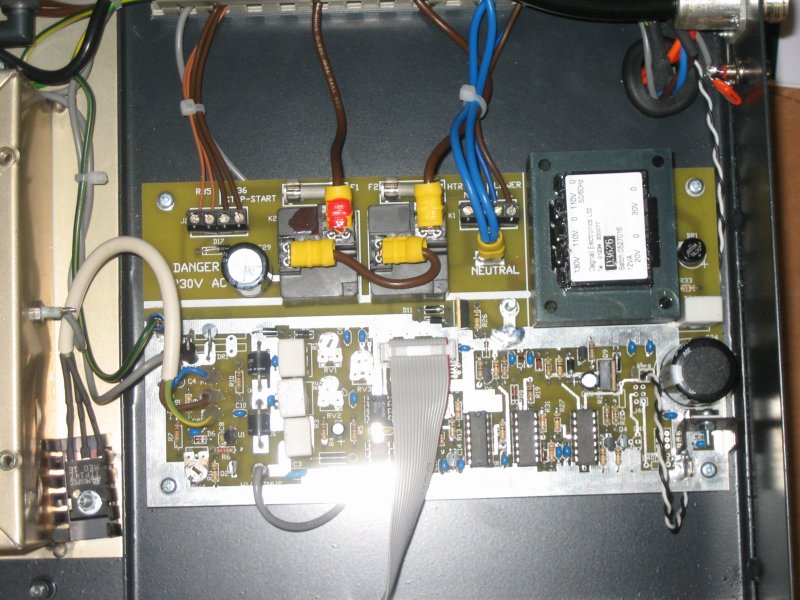
The picture below shows the best feature of the amplifier, the GM3SEK control board, it's compact and easy to understand, that is providing all rules in the manual provided with the board are complied with and user modifications are NOT applied without consultation with the boards designer!. |
||
|
|
||
| The first problem I found was this: | ||
|
|
||
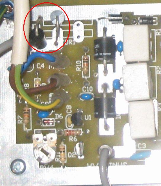
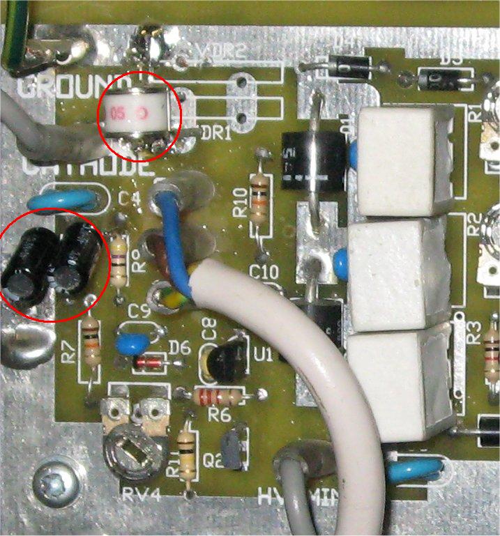
| The red circle shows where TWO VDRs should have been fitted, but from what I can tell, there looks to be two back to back diodes. | ||
| Following one of the amplifiers warranty return visits to Linear Amp UK the amp came back to me with further control board modifications, as shown here: | ||
|
|
||
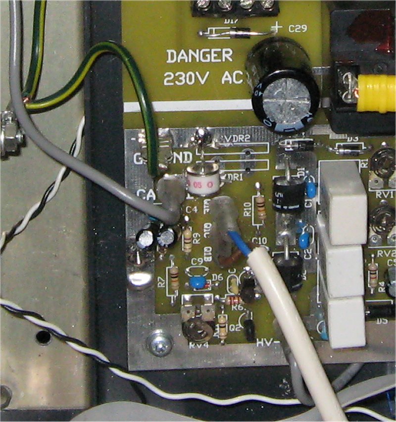
| In this picture it can
be seen how the two back to back diodes have been cut out and replaced
with some sort of gas discharge device, it's circled in red and the
device is marked with '05 O'
There's also TWO small black metal clad capacitors had also been fitted to the left of R9, in the centre left of the picture, I assume that these were an attempt to decouple R9 to ground, but I can't be sure. |
||
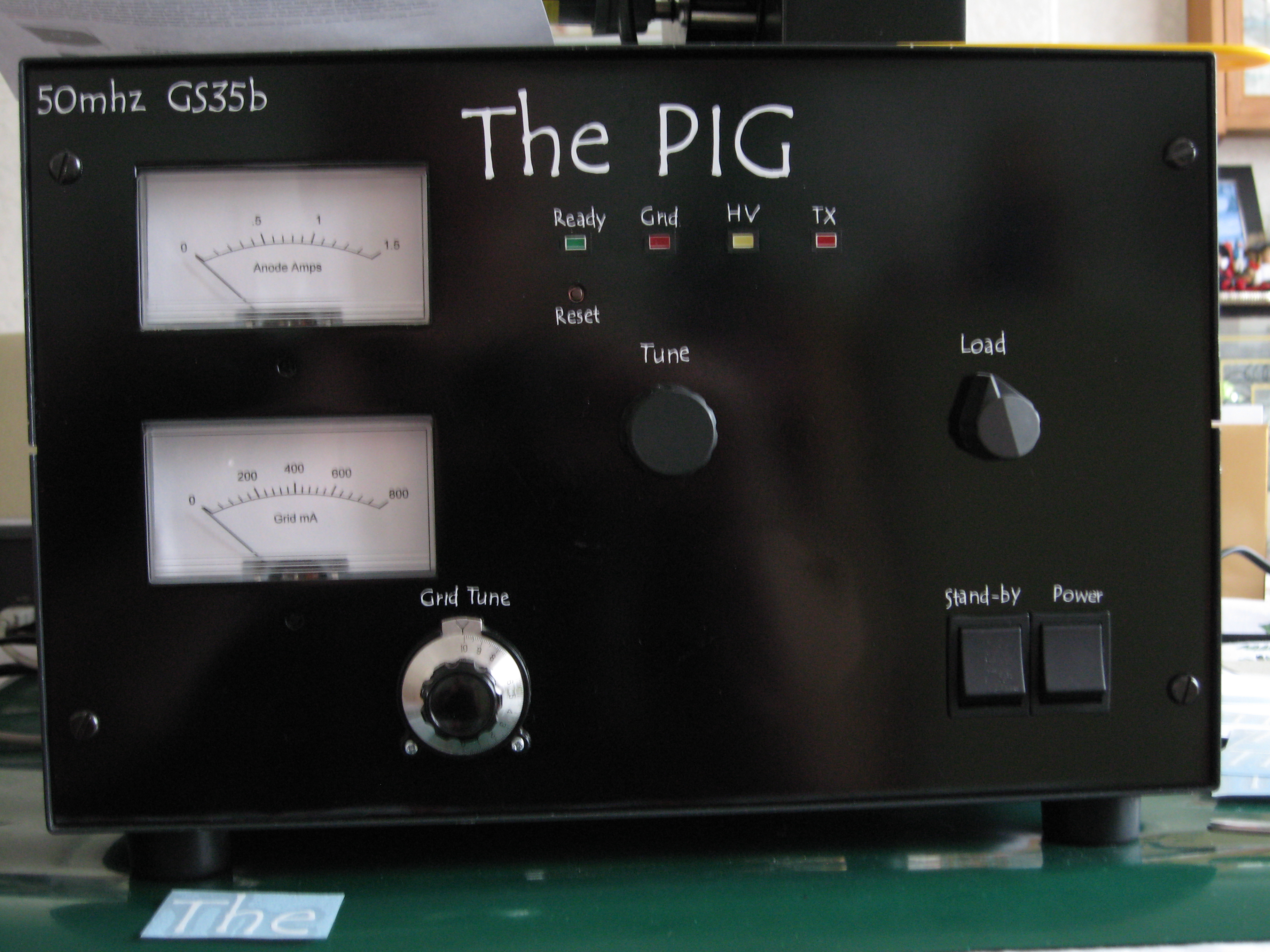
| In light of all the grief this amplifier has given me, it was hi time it was renamed. And that's just what i did, the amplifier no longer resembled a Linear Amp Discovery, it was born a pig and had lived the life of a pig. So that's what it is now, The Pig. It now performs as it should have done from the outset, but it is a new animal.
|
||
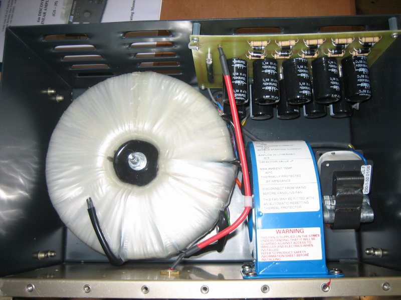
| It should be noted that I have carried out other modifications to my amplifier, but these were for personal choice rather than necessity to get the amplifier to work right. These items are the top cover exhaust vent, the power supply diode and capacitor bank, and the main transformer, front panel grid tuning, and the GS35B exhaust chimney. Details can be provided if required. | ||
|
73 Andy GD0TEP
|